All posts by npashkoff@ienga.com

2019 I-ENG-A Convention Information

Dear I-ENG-A Members:

First we would like to wish everyone a Happy New Year!

We also wanted to inform you that we are starting to plan our 2019 I-ENG-A Convention.

It looks like we are going to be having the convention in Nashville, TN this year. As for the dates, we are thinking about the first week in November but nothing is set in stone yet. We appreciate all input from members on when would be the best time frame for you to attend.

We also want to see what our members would like to discuss in terms of presentations, so if there is a topic you would like to see discussed at the convention, please feel free to let us know.

If any member would like to present a topic we are currently looking for speakers and will start reaching out to each member individually in the coming weeks.

Any and all input is extremely appreciated as we are in the early stages of planning for this convention.

We look forward to hearing from you!

T.J. Hogge
Operations Director
954-530-0715 ext. 240
tj@ienga.com

Forensic Hydrology

Forensic Hydrology

 By Elvin Aycock, PE,  PLS, ACTAR,
I-ENG-A Advisor


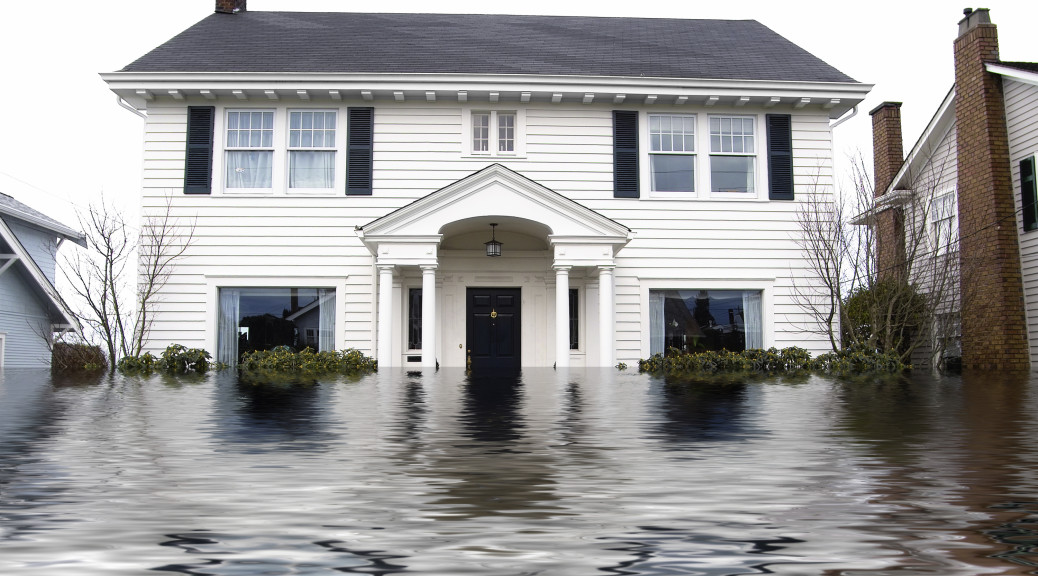
Forensic hydrologists study the causes and effects of water damage in legal cases, including flooding, erosion, drainage problems, and hydroplaning. This paper offers background on hydrology and forensic hydrology. It also provides examples of real-world situations where forensic hydrologists used their expertise to aid attorneys in legal cases.

Hydrology is the scientific study of water and its properties, distribution, and effects on the earth’s surface, in the soil, and in the atmosphere.

The central theme of hydrology is that water moves throughout the Earth in a hydrologic cycle. The most vivid image of this is in the evaporation of water from the ocean, which forms clouds. These clouds drift over land and produce rain and snow. The rainwater flows into lakes, rivers, or aquifers, either evaporating to the atmosphere or eventually flowing to the ocean, completing a cycle.

Some of the water evaporates, some of it is intercepted by vegetation, and some of it travels over the land surface to streams. The streams flow into larger streams, which flow into rivers, finally flowing back to the ocean.

Water as a liquid or snow covers most of the surface of the Earth. By the process powered by gravity and the action of solar energy, an endless exchange of water, in vapor, liquid, and solid forms, takes place between the atmosphere, the oceans, and the earth’s surface. Water circulates in the air and in the oceans, as well as above and below ground.

The quantity of rainfall varies from region to region within the United States. At the same time of year, some regions are dry from lack of rain while other parts of the country experience flooding. It is not unusual for one part of the country to experience a hurricane, while another experiences a drought, and another has flooding.

Civil engineers and hydrologists study surface water—in particular, the measurement of its flow and volume. These studies are used to design the size of pipes for storm drainage systems and culverts. Other studies include designs for detention pond storage for development projects and water surface profiles of flood prone areas.

Local governments, for example, require hydrologic studies before the commencement of all significant building projects, and hydrology is applied when designating and managing flood plains. Hydrologists also are employed in the evaluation of water resources, wastewater systems, and irrigation projects. The public use of water for recreation and power generation also calls upon the work of hydrologists, who assist governments and private companies in controlling and managing water supplies.

Hydrologists use a variety of techniques. Some are simple and time-honored, while others involve the most cutting-edge modern technology, such as highly sophisticated computer models and satellite remote-sensing technology. Or, hydrologists may apply relatively uncomplicated methods for the measurement of snow depth or the flow of rivers and streams.

Hydrologists are particularly important in helping communities protect against flooding by identifying flood hazard areas and minimizing encroachment through the use of recommended state water buffers. By studying historical records, along with geologic maps and aerial photographs, hydrologists and engineers can make recommendations regarding the zoning laws for a particular area.

Forensic hydrologists investigate many issues, including the following:

  • Flooding of property from heavy rain events
  • Development of land that prevents water from flowing in its natural watercourses
  • Erosion of the earth’s surface caused by the flow of surface water across unprotected soil created by land disturbing activities
  • Hydroplaning on roadways caused by road defects
  • Uncontrolled discharge of surface water, which causes flooding downstream

Forensic is a term that is associated with hydrology in legal matters. According to the Merriam-Webster Dictionary, “forensic” means “relating to or dealing with the application of scientific knowledge to legal problems.” In this sense, “forensic hydrology” typically refers to investigations of water issues and the need to identify the cause and damage incurred by storm water. The forensic hydrologist uses a number of hydrologic tools to determine the history of an event, such as computer modeling. He or she may need to determine when flooding began or upstream factors that have recently changed due to clearing of land for land disturbance projects.

Forensic hydrologic investigations commence with flow paths, both current and historic, and flow velocities. Changes in water flowing across the ground surface, drainage ditches, and drainage pipes often create adverse conditions downstream. The conversion of wooded land to impervious surfaces increases the quantity of storm water and the velocity of the water. The impervious area decreases the time of concentration of the water, which increases the peak flow. All of these effects can cause damage to downstream property owners.

In cases where surface hydrology has caused damage to downstream property owners, hydrologists examine historic aerial photographs to determine locations of land disturbance projects. The timeline of the downstream damage is compared with the timeline of the land disturbing activities.

For example, consider a site where soil erosion has filled in a downstream lake over a period of years. The aerial photographs help identify areas of land disturbance and the time frame for each disturbance. Where several developments have occurred over a period of years, the aerial photographs help the hydrologist identify the size of each development and the period of time the land was susceptible to erosion. The damages can be allocated to the developers based on the data gathered.

Without close oversight by the governmental agencies, developers may omit many of the erosion and sediment control measures shown on engineering plans. Because developers may have gotten away with this practice in the past, they may feel they can skip some of the erosion control measures to save money. This creates a situation where heavy thunderstorms—without appropriate control measures—can cause severe damage to downstream property owners.

A recent case that caused severe damage to the downstream property owner was caused when the developer tied a new storm drainage pipe into an existing pipe that was not adequately sized to handle the drainage from the new development. The property flooded, and the downstream landowners brought suit against the developer.

In another case, a contractor tied the discharge pipe from the detention pond into an existing storm drainage system. The existing pipe was only adequate for storms up to the 25-year storm event. The flooding problem developed because the developer did not clean out the siltation in the detention pond. Silt from erosion was allowed to accumulate in the detention pond, which decreased the volume of the storage for stormwater. When the storm event occurred, the water overflowed the emergency weir of the detention pond and flooded the downstream homeowner. The homeowner sued the developer.

Few developers understand how detention ponds function. Often, the grading contractor will not build the pond to the designed volume. This prevents the pond from being able to function as designed, and water overflows the spillway and floods the downstream residents.

Outlet structure control devices are often improperly sized or are not installed at the correct elevation. This creates a potential problem of more discharge through the outlet structure than the design model allows.

Forensic hydrologists are also called on to work hydroplaning cases. The flow of water across the pavement surface can be critical and dangerous to the motorist if the roadway surface is not constructed correctly. Often, this is a roadway defect created by improper construction methods used by the contractor.

The transition of the roadway from a tangent section to a highly elevated section can create an area of ponding. Unless viewed during or after rainfall, the area of ponding cannot be identified by the naked eye. A detailed elevation survey is needed to determine the area of ponding and the flow direction of water.

In one hydroplaning case, it was determined that the water on the roadway ran at an angle across the travel lanes onto the paved median. The water turned back and ran across the roadway again. This created a dangerous condition and caused a vehicle to hydroplane and crash into the median barrier. This section of roadway ran downgrade and entered into a highly elevated section. No inlets were provided to collect the water in the median, and as the grade increased to create the elevation, the water flowed from the paved median across the travel lanes. The depth of water on the roadway caused the vehicle to hydroplane.

The forensic hydrologist with an inquisitive mind and the use of sound engineering principles can help identify the cause that creates these types of problems. He or she can provide a valuable service to the attorney handling storm water drainage cases.

Corrosion Expertise

CORROSION EXPERTISE:  ARE YOU SUFFICIENTLY INFORMED TO  MAKE DECISIONS?

BY HERBERT H. DEFRIEZ, PE

Corrosion
Corrosion?

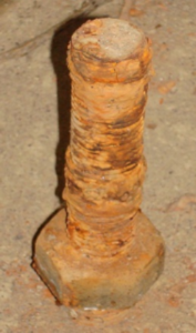
Corrosion, everybody knows what it looks like, just like the bolt shown on the right; it looks in really bad shape and if the corrosion was caused by a leak that your company insured against, this could be costly.

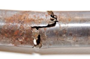
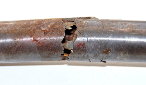
But what about things that don’t look like corrosion. Take the photo to the lower right for example. You find this piece lying on the ground after a plant accident. Looks like a mechanical failure of a brittle section of perhaps a torque tube – was this where the problem started? You take a good look, note the crystalline nature of the fractures, note the many fissures in the metal, note that the metal is mostly shiny and shows no signs of “rust”. If you concluded that this was a mechanical failure due to overstressing,

Corrosion or mechanical failure
Corrosion or mechanical failure?

you would be completely wrong. This is a section of Type 316 Stainless Steel tubing carrying smoke stack gases to an analyzer. The fractures are actually chloride-induced stress corrosion cracking and the disruption was caused when a pipe fitting was being removed by hand. Not your culprit at all.

And these revelations about corrosion can go on and on. To give you the most basic insight into the potential problems in assessing corrosion, let’s start by just listing the nine general forms of corrosion, (probably many more than you thought and way more than you wanted to know). Corrosion comes in the following forms: 1) Uniform (like bolt shown); 2) Localized (pitting); 3) Galvanic (connecting brass to steel); 4) Velocity Induced; (erosion corrosion) 5) Intergranular; 6) De-Alloying; 7) Cracking; 8) High Temperature and 9) Microbial. The items not followed by an example are the more difficult types to evaluate and often require sophisticated analysis to determine. If your company has corrosion exclusions in its property policies, could you recognize if corrosion were involved and recommend a cause and origin investigation?

An actual example involves a sail boat mast failure in high winds. Clearly the cause was the wind but the policy had a corrosion exclusion. The broken section was sent for evaluation. Dismantling the stainless steel sail retainer and its stainless rivets from the aluminum mast exposed exterior corrosion at each rivet hole. Micro sectioning also reveled cracking around each hole; these cracks were the probable initiation point for a massive tension failure. Perhaps without the corrosion induced cracks, the mast would not have failed? The insurance company did not pay.

Fortunately, your I-ENG-A family of investigators has a Registered Corrosion Engineer – myself. I can work through your local investigator to provide evaluations of simple-to-complex corrosion problems. Once engaged, I would prepare inspection, photograph and interview criteria for the local investigative engineer to perform on-site. Over 80 percent of the time, the origin and cause can be determined over the Internet using this locally collected data. Should the problem exceed this approach, I can also travel to photograph and retrieve samples for sophisticated chemical and physical analysis. Should subrogation become an issue, I am also a court-tested expert witness. Contact your local I-ENG-A member for details.

By the way, about the bolt. You would most likely have been wrong about it as well. This bolt was submerged in water for nearly two years in a newly poured concrete footing sump. The water’s alkalinity prevented most of the uniform corrosion that would have occurred under other circumstances. After drying out, the bulk of the “corrosion” appeared to be silt and hydrated lime, easily removed with a wire brush. The cleaned bolts would easily accept new nuts. To verify that the bolts were still suitable for their originally intended purpose, in-place pull tests were performed; these tests indicated the bolt’s strength was still in excess of design specifications. After only cleaning, the bolts were returned to service. These results would have saved you a lot of money.

 chloride-induced stress corrosion cracking
Chloride-Induced Stress Corrosion Cracking

About the Author:

Mr. Herbert H. DeFriez, P.E., graduated from the University of California, Berkeley, with a BS in Chemical Engineering in 1966 after surviving the Free Speech Movement and Mario Savio standing on a police car in Sproul Plaza. Disliking chemical engineering, his first job was as a corrosion engineer with American Potash and Chemical in Trona, CA. Since there were no women above high school age in town (if you have been to Trona, you know why), he returned to chemical engineering as an experimental operations engineer with Shell Development in Albany, CA. With the Vietnam War at its height and Mr. DeFriez’s allergy to bullets, he joined the U.S.Public Health Service as alternate service where he learned industrial hygiene sampling – this lead to the beginning of his career in environmental engineering. First as an employee that developed an air and water testing laboratory, then as a consultant to that laboratory, then on to developing a design and manufacturing company that built air sampling and testing equipment and to owning a second company that performed source emission testing – all over a mere forty years.


Along the way, Mr. DeFriez continued to be involved in corrosion projects, eventually applying to be grandfathered into the new California Profession Engineer’s Corrosion Engineering specialty. Over the years, he has been the principal engineer in a number of legal involvements, only a few resulting in testimony in court (best way to do it). As he likes to say, “I have always won my cases, sometimes by a positive judgment and sometimes by telling my client that he has no chance, so don’t spend any more money”.


In the environmental field, Mr. DeFriez has gathered three patents, one for an analytical procedure and two for instruments or sampling equipment. His association with I-ENG-A is through this company. Since he really enjoyed the investigative aspect of corrosion projects, he considered the prospect of investigative engineering past his retirement age a positive development to keep him active and alive (needed since he has a much younger Chem E wife who wants him around for some while).

Accident Reconstruction

Accident Reconstruction: Enhancing Results

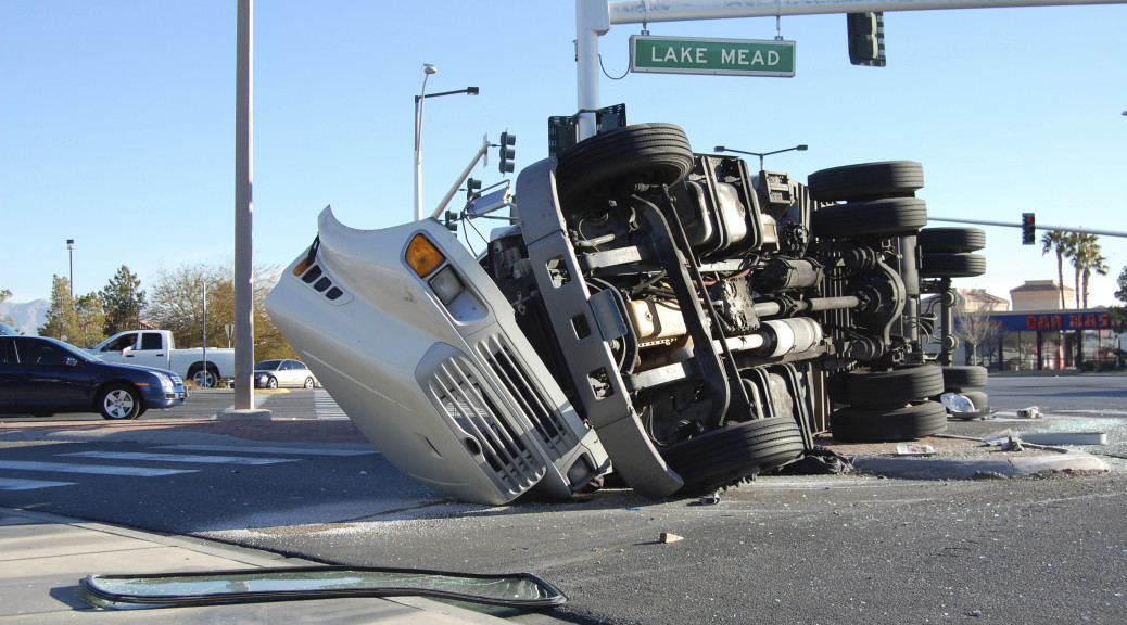
Automobile accident reconstruction can be simplified by following some specific practices. Good documentation of the physical evidence leads to a thorough understanding of the vehicles’ motion before and after an impact. Poor documentation of the evidence may complicate and, in some cases, make a full reconstruction impossible. The accuracy of a reconstruction is largely dependent on the quality and preservation of the physical evidence.

There are three phases to most automobile accidents: pre-collision, collision and post-collision. When investigating an accident, there are distinct physical evidence patterns that should be documented for each phase. Measurement and photographs of the evidence is then used to assess vehicle motion.

Pre-Collision:

Vehicles are often at their tire adhesion limit before a collision occurs, whether it is full braking, full yawing (cornering) or a combination. When tires are at their limits, they leave rubber on the road in the form of skid marks and/or yaw marks. Skid marks are straight (the tire is locked up and cannot turn the car). Yaw marks are curved (the car is fishtailing). Most modern vehicles have antilock braking systems, which prevent wheel lock and reduce the likelihood of finding pre-collision skid marks.

The length and character of this pre-collision evidence usually represents energy loss. In other words, when a vehicle locks its brakes, it loses energy and speed. When a vehicle is fishtailing it also loses energy, dependent upon its slip angle, i.e., the more sideways it gets, the more energy it loses. Published coefficient of friction values on different surfaces help understand the energy loss.

Collision:

When a vehicle collides with an object or another vehicle, it deforms. The exact amount of this deformation also represents energy loss. Collision damage can often be compared to crash test data, in which the energy loss is a known quantity. For example, if a car crushes 20 inches during a frontal collision and that same model crushed 20 inches in a 30 mph barrier impact test, then the collision energy loss is equal, even though other dynamics may be different.

Measurement of the crush damage is compared to an undamaged vehicle. Measurement accuracy and detailed photographs can greatly influence the reconstruction. Some late model vehicles have black boxes onboard that record speed loss, which can be used to confirm crush energy calculations.

Post Collision:

After collision, damaged vehicles cause surface gouges/scrapes, drag marks, fluid trails and debris trails, all of which help understand post-collision motion. The nature of sliding contact with pavement and/or grass/dirt changes the energy loss. The harder a vehicle drags/scrapes the surface, the more energy it loses. Resulting surface damage and the corresponding vehicle component should be determined.

All three accident reconstruction phases and their associated energy loses are added up to give the initial vehicle sped (total energy). Careful documentation of each accident phase combined with the basic laws of physics will enhance auto accident reconstruction results.

By:  Elvin Aycock, PE, ACTAR, I-ENG-A Accident Reconstruction Advisor

Building Science: The Life and Death of a Building

Building Science, Building Enclosure, Building Envelope Monitoring

It’s a familiar scenario in science fiction novels and movies: A catastrophic event of some kind occurs, and Earth’s human population is wiped out, leaving the rest of the world intact. What would happen then?  Nature would get on just fine without us. Though our family pets might find it challenging to fend for themselves, wild animals would proliferate, and vegetation and forest cover would thrive and spread.

But what about the built environment? Just like the common automobile, ski slope, or nuclear reactor, buildings and infrastructure need our constant care and maintenance. Without it, the natural elements would ravage our structures, which would effectively die and be swallowed by nature completely.

Within just two to five years of neglect, most buildings would show evidence of water damage. With no one to maintain building grounds, unchecked plant and tree growth against a structure would lead to an increase in moisture levels. High moisture content means harmful growth of molds, mildew, algae and even creeping plants that can cause cracking in the building’s exterior, leading to water penetration.

Untamed vegetation wouldn’t be the only threat. Exposure to weather over time would also lead to decay. Without regular maintenance, rain, wind, sun exposure and frost could cause corrosion and cracking on the exterior of a building, leading to even more opportunities for water damage.

Within just 15 to 20 years, dramatic building envelope damage would be evident. Once a building’s envelope is compromised, the natural elements are able to work their way inside a building, causing interior walls and ceilings to swell and crack or sag, leading to eventual collapse of the structure.

Though most buildings aren’t so completely neglected as suggested in our science fiction scenario, it helps to illustrate how a little proactive building maintenance can prevent costly structural failures down the road.

SMT’s Investigative Monitoring solution makes it possible and economical to monitor the health and performance of commercial and residential structures, and provide early warning detection on structural failures.

Using a variety of on-site sensors that measure factors such as moisture, differential pressure, temperature and humidity, SMT’s technology monitors a building system over time, and analyzes data online. When a problem is detected, wired or wireless electronics provide feedback in real time, with status reports sent directly to your email inbox.

Construction liability for moisture and mold is on the rise, and insurers are responding by eliminating water damage coverage from their policies. With SMT’s early warning moisture detection system, building owners and other stakeholders are made aware of their building’s moisture characteristics and accumulation locations, and can take action before moisture causes severe damage. Changes in weather and other environmental factors are automatically correlated to moisture-related events within the structure that is being monitored.

The parameters of temperature, relative humidity and direct material moisture content are of primary concern for long-term monitoring, investigation and risk mitigation. The temperature and relative humidity sensors enable the monitoring of the wall or roof cavity air space conditions including dew points, vapor pressure and condensation potential. The direct moisture content gives the amount of moisture in the external wall sheathing which can come from exterior leaks in the cladding or from condensation or moisture sources from the interior occupants.

SMT’s Building Analytics on-line monitoring center provides data collection, processing, analysis, graphical display and long term storage of sensor data. Analytics tracks the state of each job and sensor to alert users promptly when issues arise. Automated reports, drawing sensor overlay status and dashboard information presentation make the Building Analytics web based software a key to understand the information coming from the sensors.

Communication from the sensors and data acquisition system internal to the Building Analytics On-line Monitoring Center can be achieved mainly by two methods: wireless live or wireless data logging communication.

Wireless Live Communication

Wireless live communication is an excellent solution for short or long term monitoring in any type of structure with-in the approximate 300 foot wireless coverage to the Building Intelligence Gateway (BiG), pending wall types and wireless interference which are installation site specific. An extension receiver or repeater can be installed with-in the building to expand the area of coverage from the wireless system. Most common areas of wireless extension coverage are located on roof tops or through vertical risers to reach sensors and A2 data acquisition nodes on different floors.

The A2 node endpoints do not need reprogramming or configuration when entering a Wireless Point to Point (live) network from a Data logging remote data collection methodology – this feature is excellent for transition from construction monitoring to permanent long term monitoring projects at a low cost.

Wireless Data Logging Communication

Wireless Data Logging systems enable the sensors and data acquisition hardware to be installed in sparse configurations, and installed in specific areas of interest, eliminating the immediate need to install communication wires or wireless receivers permanently or semi-permanently in the building. The wireless data logging equipment can be embedded in the wall, roof or alternative areas located with-in which are hard to access or require permission to retrieve. The sensors and acquisition system can be installed on high elevations on the side of the building or located within private suites.

Simply bringing a notebook PC with a receiver into the proximity of 300 feet (pending on construction type) from the sensor location retrieves the data through wireless means. The physical access to the data logger is no longer required to retrieve data as in the case of USB data loggers. The expense of a permanently installed remote gateway and site Internet connection is eliminated.

Our real-time sensor analysis and remote data collection enable engineers and researchers to validate their designs, materials and methods, while reinforcing quality assurance throughout varied forms of construction & renovation. This creates more efficient buildings, with a lower environmental impact and monetary cost.

Building intelligence monitoring kits can be installed during or after construction, and can be tailored for each project. The monitoring systems are a cost-effective way to have detailed information about a structure made available at your fingertips. This information can help you extend the life of your building.

This technology can have great value to Investigative Engineers, Insurance Carriers and Self Insured Companies in properly assessing their claims and mitigating additional building damages in the future.

Additional technical information is available for member firms in the www.ienga.com video library recorded from Convention 2010.

Article By:  Jason Teetaert, P.Eng., Structural Monitoring Technology